FDM holes print about 0.25 mm undersized in the one test that discloses its method
The number to start with: a hole modeled at 4.0 mm and printed in PLA on a Prusa CORE One L came out about 0.25 mm undersized. That’s from CNC Kitchen’s recent heat-set insert test, which printed three samples at each diameter from 3.6 to 4.6 mm, used drill bits as go/no-go gauges to check the actual bore, and pulled every insert to failure on a tensile tester afterward. The material was Polymaker PolySonic PLA, the machine a stock CORE One L, and the finding held across the diameter range tested, not just at one size. That combination, disclosed material, disclosed machine, a real measurement tool instead of a caliper guess at a round hole, and enough samples to call it a pattern, is rarer than it should be in this corner of the industry. Most of what’s published about hole undersizing is a design-guide rule of thumb with no printer named and no sample count given.
The rest of this piece sorts out what’s measured from what’s claimed, process by process, and ends with numbers you can actually type into a slicer or a CAD file.
FDM: one disclosed test, several undisclosed ones
CNC Kitchen’s 0.25 mm figure is specific to one machine, one filament, and a hole range built for M3 inserts. It will not transfer exactly to a 0.4 mm nozzle running ABS at 220 mm/s, and nobody should assume it does. But it is the only FDM number in general circulation that names the printer, the material, the measurement method and the sample count.
Everything else is softer. A hobbyist shrinkage test on Printables, run with Overture PLA Rock and checked by caliper, found the undersizing is not constant across diameters: it measured around 0.35 mm of shrinkage at the smallest hole tested, dropping to roughly 0.08 mm by the time the hole reached 5 mm and above. That tracks with the direction every academic study agrees on without exception, that the mean deviation gets worse as the hole gets smaller, a relationship a 2023 Applied Sciences study by Popescu and colleagues confirmed when testing counterbore holes from 6 to 10 mm on FFF hardware, and again on a second test part with 2.3, 4.5 and 6.5 mm holes, all of which came out undersized regardless of shell count or layer thickness. Neither of those sources gives the clean single number CNC Kitchen’s test does, because the deviation moves with diameter instead of sitting still.
A third figure worth naming because it circulates widely without any disclosed test behind it: RapidDirect’s design-guide blog states FDM holes measure 0.1 to 0.3 mm smaller than modeled, as a flat range with no printer, material or sample count attached. It’s a reasonable midpoint estimate and it roughly brackets both the CNC Kitchen number and the Printables test, but it is a compiled claim, not a result you could reproduce from the page.
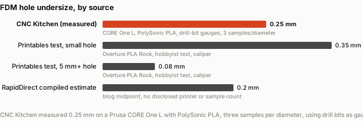
If you only trust one FDM number, trust the one with a named printer and a disclosed sample count. Use the Printables-style diameter curve as a sanity check on direction, not magnitude, since it’s one hobbyist, one filament, one printer.
SLS: shop-floor numbers, tighter than the slicer-era FDM figures
Selective laser sintering comes from a different manufacturing culture, powder-bed service bureaus that have been quoting tolerances to paying customers for two decades, and it shows in how concrete the numbers are. A write-up of problems and fixes on an EOS P-series line (two P 396/P 400 machines plus HP MJF units, run by the contract shop JawsTec) states a typical SLS tolerance of plus or minus 0.1 mm, with the same figure given specifically for hole diameter, and adds that holes and the parts meant to mate with them need about 0.2 mm of play to actually go together after the powder is cleaned out.
Design guides built around running EOS machines day to day, rather than selling printers, converge on a looser but still usable range: plus or minus 0.3 mm or 0.3% of the dimension, whichever is larger, which is the figure in Forgelabs’ SLS guide and echoed by Hubs and PrintForm’s service pages. A UK bureau running PA12 on SLS separately notes that small holes under 10 mm diameter tend to come out slightly elliptical on the side facing up the Z axis, a geometric detail that a simple plus-or-minus number doesn’t capture but that matters if a hole has to take a round pin rather than a loose bolt.
None of these SLS figures discloses a sample count or a named test part the way CNC Kitchen’s FDM test does. They read as operational experience from running production machines, which is worth more than a printer manufacturer’s marketing page, but it is still short of a controlled measurement.
MJF: a 0.2 to 0.4 mm claim nobody has shown their work on
Multi Jet Fusion tolerance numbers are the most consistent across sources and the least independently verified. HP’s own design guide and the Xometry and SyBridge pages built on it quote a general tolerance of plus or minus 0.3% with a 0.2 mm floor, with holes called out separately as prone to printing undersized because the fused polymer ring around a hole shrinks toward its own center as it cools, a mechanism a consultancy write-up (RapidMade) describes in detail, putting a 5.0 mm modeled hole at 4.7 to 4.8 mm as printed and recommending 0.15 to 0.3 mm of added diameter to compensate. A separate comparison table pegs MJF hole undersizing at 0.2 to 0.4 mm against 0.3 to 0.5 mm for SLS, calling MJF the tighter of the two powder processes on this one feature.
All of these numbers describe the same mechanism in the same language and land in the same 0.2 to 0.4 mm band, which is reassuring as a consensus but not the same thing as a disclosed test. None of the sources above names a specific printer run, a sample size, or a measurement instrument for the hole figures; they read as inherited design-guide wisdom passed between service bureau websites. Take the 0.2 to 0.4 mm range as the working number, and treat the 4.7 to 4.8 mm example as illustrative rather than a verified average.
SLA: tight on paper, unmeasured for holes where it counts
Formlabs’ current design guide for the Form 4 gives a general dimensional tolerance of plus or minus 0.15% (floor 0.02 mm) for features between 1 and 30 mm, and separately recommends a minimum hole diameter of 0.5 mm, down from 0.42 mm on the Form 3 in the same side-by-side table. Neither of those numbers is a measured hole-undersizing figure; they’re a general accuracy spec and a minimum-feature recommendation, which is a different question from how far off a 5 mm through-hole actually lands.
Ask on Formlabs’ own community forum what the real hole tolerance looks like and the best answer offered is theoretical: half the laser spot diameter, which works out to roughly 0.15 mm for a Form 2 and 0.05 mm for a Form 3, with the same poster noting that resin trapped and over-cured inside a hole is usually the bigger practical problem than the nominal laser-spot number. That’s a forum estimate from a long-time user, not a published test.
The closest thing to an independent measured result comes from a 2024 study (published via PMC) that scanned stereolithography parts printed in a castable wax resin at three build orientations and found hole features showed the smallest deviation of any geometry type tested, with the lowest error, 1.98%, at a 45-degree build angle, against larger deviations of 4.8 to 7.3% for cylindrical and spherical features. That’s genuinely useful as a direction (SLA holes deviate less than other round features, and orientation matters), but it’s a different resin from what most desktop and benchtop users run, and it doesn’t give a millimeter number for a hole at a stated nominal diameter. We could not find a published SLA test that does what CNC Kitchen’s FDM test does: name the resin, name the machine, state a sample count, and report a hole diameter in millimeters before and after printing. That’s the real gap in this piece, and it’s worth saying plainly rather than filling it with a guess.
What to type into the slicer or CAD
For FDM, start at +0.25 mm on hole diameter if your material and machine are reasonably close to PLA on a well-tuned desktop or benchtop printer, the one figure here with a disclosed test behind it, and shift toward +0.3 to +0.35 mm if the hole is small (under 3 mm) or the filament is a stiffer engineering material prone to more shrinkage. For SLS, +0.1 mm covers a snug hole on a well-run EOS-class machine; add up to 0.2 mm of play if the hole has to clear a pin or bolt after depowdering, and expect small holes under 10 mm to print slightly elliptical rather than round. For MJF, +0.2 to +0.3 mm is the working range across every vendor source we found, with nobody publishing the disclosed test to pin it down further. For SLA, there is no equivalent trustworthy millimeter figure; start from Formlabs’ 0.5 mm minimum-hole recommendation and the general 0.15% tolerance band, and budget extra margin if the hole is horizontal, since resin pooling and over-cure inside a horizontal bore is the failure mode every source agrees on even without a hard number attached to it.
Whatever number you pick, print a short test coupon with three to five holes spanning your actual diameter range before committing to a production part, measure each one with a pin gauge or a drill bit rather than eyeballing a caliper against a round edge, and re-run the check any time you change material lot, nozzle, or resin batch. CNC Kitchen’s test is convincing partly because it used a physical go/no-go gauge instead of a caliper reading on a circular hole, which is easy to get wrong by a few hundredths of a millimeter in exactly the range that decides whether an insert seats flush or cracks the part.
Sources
- https://www.cnckitchen.com/blog/are-our-heat-set-insert-datasheets-wrong
- https://www.printables.com/model/449520-hole-diameter-shrinkage-test
- https://www.rapiddirect.com/blog/3d-printing-tolerances-how-accurate-is-3d-printing/
- https://www.researchgate.net/publication/366484030_Investigations_on_Factors_Affecting_3D-Printed_Holes_Dimensional_Accuracy_and_Repeatability
- https://www.stratasys.com/siteassets/fdm-system/fdm-3d-printers-materials-spec-sheet.pdf
- https://3dprint.com/243316/sls-3d-printing-problems-and-solutions/
- https://www.3dpeople.uk/pa12-nylon-sls/
- https://www.3dprint-uk.co.uk/sls-pa12-pa2200-nylon/
- https://forgelabs.com/design-guides/sls
- https://rapidmade.com/comprehensive-analysis-of-as-printed-tolerances-in-multi-jet-fusion-mjf/
- https://layerx3d.in/blog/hp-mjf-design-rules-wall-thickness-tolerances-geometry
- https://f.hubspotusercontent00.net/hubfs/340051/Design_Guides/Xometry-HP-MJF-DesignGuide.pdf
- https://formlabs.com/white-papers/form-4-design-guide/
- https://forum.formlabs.com/t/communicating-form3-printed-part-tolerances-to-customers/29331
- https://www.ncbi.nlm.nih.gov/pmc/articles/PMC11644789/
- https://jlc3dp.com/help/article/3d-printing-design-guideline